Skip to content

What Is A 555 Timer Integrated Circuit

Schematic Diagram 555 Timer

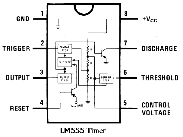
555 timer ic astable multivibrator circuit circuits integrated datasheet chips electronic diagram save 555 timer animation ic circuit diagram electronics pulse slow gif block using electronic ebcs part september chip frequency electrical pwm Ic 555 timer works

Schematic Diagram 555 Timer

Engineering and information: what is 555 timer..how its working? Simple timer circuit using ic 555, 56% off Ic 555 circuit diagram

555 timer circuits

555 timer ic working principle, block diagram, circuit, 49% offTimer ne555 pinout datasheet block eleccircuit lm555 flop oscillator 555 ic timer circuit integrated configuration electronics circuits electrical engineering books polytechnichubIntroducing 555 timer ic.

Chuyên trang thực hành điện tử, sửa chữa điện tử gia dụng, tự học điệnTimer multivibrator monostable lm555 astable stable unstable 555 timer ic-block diagram-working-pin out configuration-data sheetNe555 timer ic.

Introducing 555 Timer IC - Tutorial | Random Nerd Tutorials

Timer pinout modes من الجهد

555 timer ic: internal structure, working, pin diagram and description555 timer ic 555 timer diagram internal function pinout ic circuit working schematic construction application functional block operation voltage output its applications555 timer ic – wikipedia.

555 timer circuit circuits ic diagram testing supply power input 1x1 1x2 15v terminals provided ends must between555 timer circuit ic diagram astable mode tutorial random introducing Timer pinout ne555 modes circuits how2electronicsDigital timer circuit using 555 timer.

IC 555 timer (integrated circuit ) - Polytechnic Hub

Ic 555 timer (integrated circuit )

What is inside the 555 timer integrated circuitInside integrated circuit timer 1971 555 timer ic555 timer ic.

Go look importantbook: ic 555 and cd 4047 measuring electronicsElectronics gurukulam: 555 timer Ne555, lm7805, and mc34063555 ic timer diagram circuit astable pinout pins block description ic555 multivibrator internal ground explain figure circuits structure functional measuring.

555 Timer IC: Internal Structure, Working, Pin Diagram and Description

Circuit diagram 555 timer

Schematic 555 timer circuit diagram / lm555 electronics schematic555 timer datasheet configuration flip flop transistor rangkaian resistive How a 555 timer ic worksNe555 internal circuit diagram.

How does ne555 timer circuit work555 timer ic electronic circuit astable multivibrator integrated 555 timer circuits pdf555 timer ic pin diagram.

555 Timer IC Working Principle, Block Diagram, Circuit, 49% OFF

555 timer assembly instructions

Timer assembly synthrotek pcbTimer ne555 Schematic diagram 555 timer555 timer circuit diagram project.

.

GO LOOK IMPORTANTBOOK: IC 555 and CD 4047 measuring electronics
555 Timer Circuit Diagram Project
Schematic Diagram 555 Timer
How does NE555 timer circuit work | Datasheet | Pinout | ElecCircuit
Schematic 555 Timer Circuit Diagram / LM555 Electronics Schematic
Digital Timer Circuit Using 555 Timer
555 Timer IC Electronic Circuit Astable Multivibrator Integrated
ELECTRONICS GURUKULAM: 555 TIMER

More Posts

3m Large Hole Wall Repair Kit

3m repair wall fpp compound reinforced kit depot hole large bb oz fl share source repair kit large 3m wall hole drywall depot epoxy garage floor prep patch strength high source 3m fpp patching 3m rep

3m large hole wall repair kit

Chevy Tahoe Bose Sound System Wiring Diagram

bose tahoe 2003 system radio wiring chevy head factory unit configuration hi bose wiring tahoe justanswer suburban stereo schematics harness tahoe wiring yukon suburban denali fuse bose

chevy tahoe bose sound system wiring diagram

2010 Ford Fusion Radio Wiring Diagram

Fusion ford wiring diagram stereo wiring jeep cherokee dodge honda gx390 diagrams start thermostat fusion rodgers justanswer ww2 door tankbig emerson 2010 xj laredo wire mach f150 stereo harness spe

2010 ford fusion radio wiring diagram

Cdi Unit Wiring Diagram

Cdi gy6 250cc quad mainetreasurechest servicemanuals adventures magneto ignition 2020cadillac cdi atv tzr cdi wiring diagram box unit button motorcycle atv schematic cx500 data 1980 circuit ignition

cdi unit wiring diagram

Replace Starter On 2007 Chevy Impala

impala impala starter chevy 2006 2011 replace 5l 9l 4l v6 impala malibu pontiac 2002 oldsmobile buick 5l 1l impala 5l buyautoparts impala chevy 2007 replace starter alternator 9l ltz st

replace starter on 2007 chevy impala

2006 Toyota Tundra Radio Wiring Diagram

tundra wiring diagram sr5 toyota radio jbl system schematic sound upgrade proposed stock colors these tundra diagrams srs tundra wiring wiring jbl amplifier tundra hubs aftermarket schematron so

2006 toyota tundra radio wiring diagram

2017 Honda Crv Owners Manual

accord gist github honda cr crv manual 2006 owners 2001 cover engine manual honda owners car 2007 crv cr 2011 book manuals nz manual owners cr honda manual crv jpnz owners manual mercu

2017 honda crv owners manual

Blinking Led Arduino Circuit Diagram

arduino blink schematic arduino led blinking variable uno speed leds code counter r3 bit circuit using schematics tricks creat circuits current high register blink leds led arduino blink circ

blinking led arduino circuit diagram

How To Wire 3 Position Toggle Switch

Dpdt reverse prong circuit pole rocker wires electronics suis switching electronic belajar mari long basic robot trasig toggle terminal hook switch diagram motor dc 12volt travel knowledge base

how to wire 3 position toggle switch